Two LCD modules can share a similar size or a 128 × 64 dot format and still be different products. The driver IC may be packaged differently, the PCB connection may change, and the space left for the bezel, backlight and enclosure may not match. For OEM equipment, construction belongs in the specification—not after the outline is frozen.
This guide explains chip-on-glass (COG) and chip-on-board (COB) LCD modules, when each path is a better starting point, and what an engineering review needs before samples are ordered.
What COG and COB Actually Describe
COG and COB describe how the driver IC is attached. They are not optical modes such as TN, STN, FSTN or VA, and they are not interface names such as SPI or parallel.
| Decision point | COG starting point | COB starting point | Confirm before selecting |
|---|---|---|---|
| IC mounting | Driver bonded to LCD glass | Driver mounted on a PCB attached to the glass | Driver and controller availability over the product lifecycle |
| Mechanical envelope | Often thinner, with less board area | Usually includes a board, mounting points or header | Outline, viewing area, thickness, mounting and enclosure clearance |
| Host connection | Often routed through an FPC or designed interconnect | Often a pin header or board connector | Exact pinout, interface, voltage and connector geometry |
| Integration path | Useful when enclosure space and border are constrained | Useful when a board-style module fits the assembly | Real host PCB, firmware, backlight and validation sample |
In a COG (chip-on-glass) module, the driver IC is bonded directly to the LCD glass. The glass carries the pixel or segment pattern and the traces that reach the chip. A COG assembly is often thinner, with a smaller border around the viewing area, which can suit compact instruments, handhelds and tight control panels.
In a COB (chip-on-board) module, the driver IC is mounted on a printed circuit board and usually covered with encapsulant. Many catalog character and graphic modules use this construction. The board can make a pin header, mounting holes and backlight easier to integrate, but the module is often thicker than a comparable COG design.
Connection method is a third decision. CXW Display reviews COG, COB and connector options together, including PIN, elastomeric (zebra) and FPC connections. A COG assembly may still exit through an FPC; a COB module may use pin headers. Choosing COG does not define the connector, and choosing COB does not make a module compatible with an older pinout.
Review segment and graphic LCD options Check FPC and connector design details
Sources: Newhaven Display LCD assembly types
Construction Is Not a Substitute for Compatibility
Matching the size, or even the resolution, is not enough. Two 128 × 64 or 240 × 160 modules can use different controllers, pin assignments, voltages, initialization, viewing directions, polarizers and outlines.
- Viewing area, glass outline, thickness and mounting or bezel constraints
- Interface, controller or drive method, voltage and pin assignment
- Optical mode, viewing direction, contrast target and backlight requirement
- Operating environment, including temperature and how the module is held
- Sample quantity, annual demand and expected production lifecycle
CXW Display's monochrome review starts from the drawing, artwork or reference sample, then brings optical, electrical, mechanical and supply requirements into one specification. Final values are confirmed against the application.
When COG Is the Better Starting Point
COG is often a practical path when space is tight, or when the display must sit close to a window, lens or keypad with little unused border. The flex can be routed to a connector location that suits the PCB rather than a fixed pin grid.
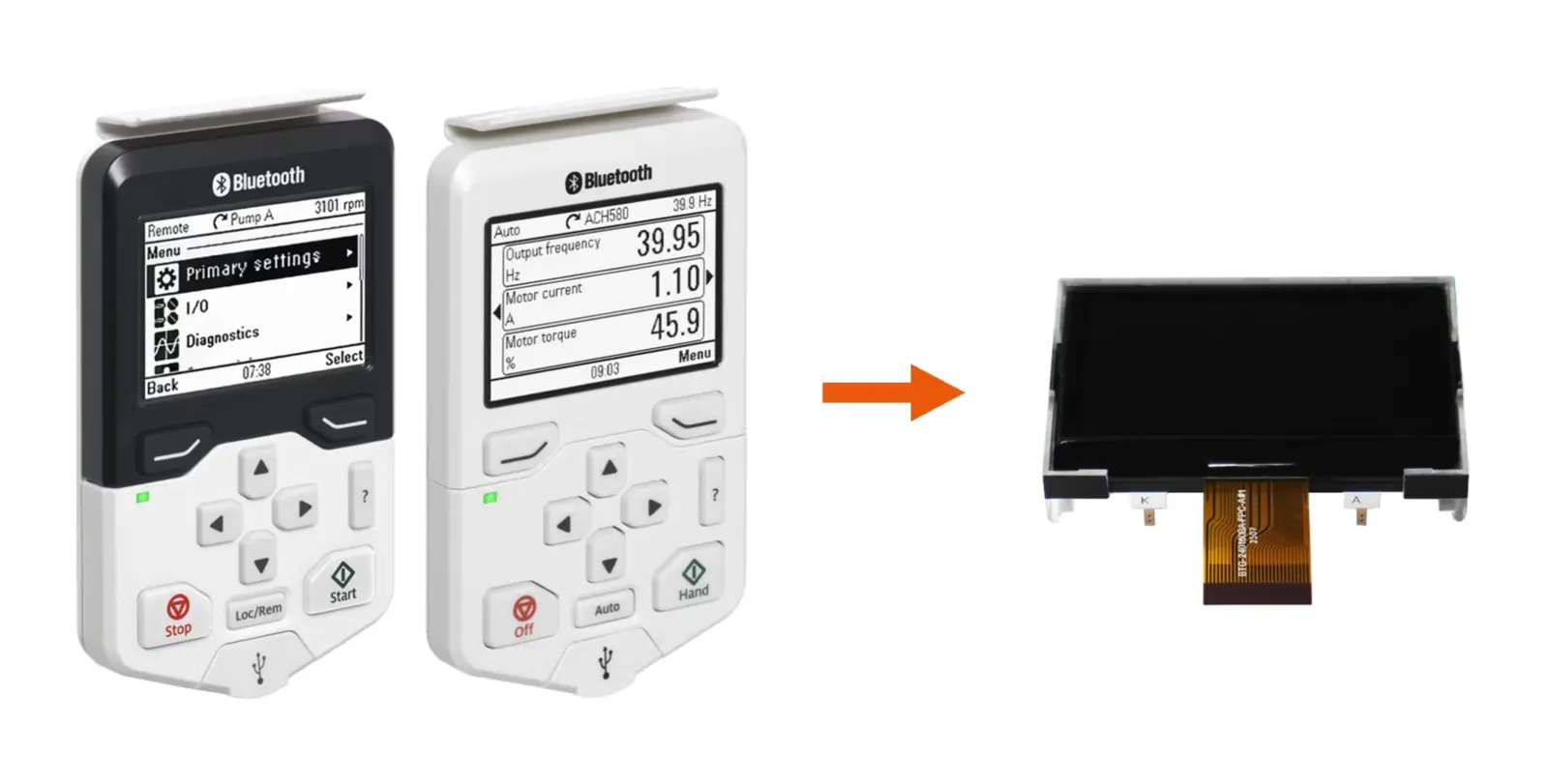
One published CXW example is the CXWRTL02838NKW010 240 × 160 DFSTN COG graphic module with a 3.3 V parallel interface, offered as a replacement LCD component for compatible industrial control-panel revisions. It also shows the necessary caution: the equipment model name is not enough. Compare the original outline, flex, pin assignment and panel revision.
COG is not automatically more advanced, and it is not always lower power. Power depends on the drive scheme, controller, backlight and host electronics. Confirm it on the assembled product.
When COB—or a Pin-Connected Module—Is the Better Starting Point
COB remains a strong path when the product can use a proven board-style module, when through-hole pins simplify assembly, or when the team already has a driver for a familiar character or graphic format.
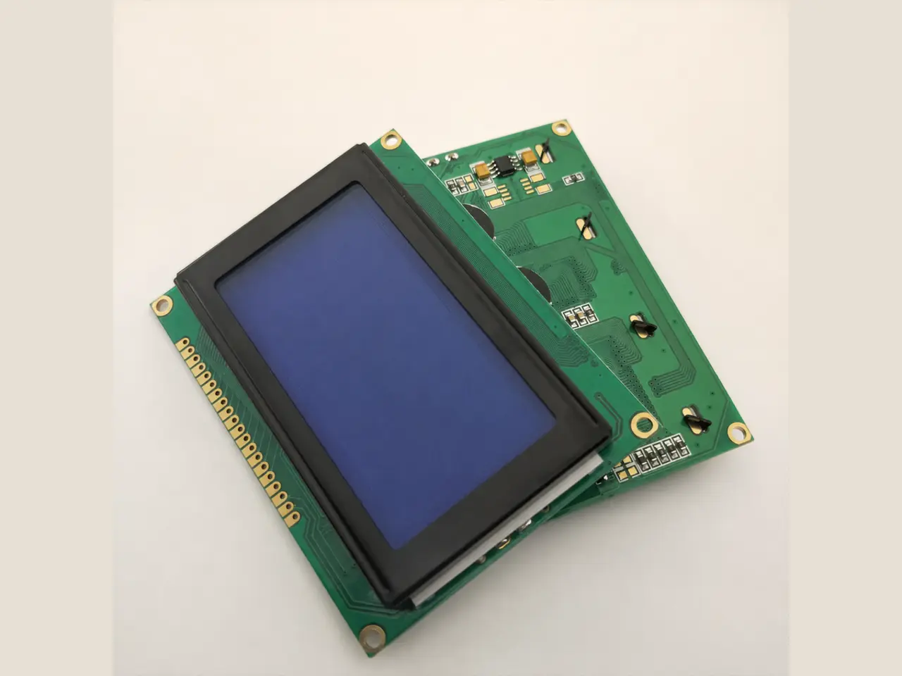
A 128 × 64 STN COB graphic module or a 20 × 4 character COB module can be a fast way to get a readable interface onto a control board—if the outline, pinout, voltage and viewing direction actually match. These catalog examples are different products from the 240 × 160 COG example above; they are not proposed drop-in alternatives.
PIN-connected monochrome glass is another option when the display mounts directly to a PCB and the artwork is project-specific. The important decisions are the layout, optical mode, viewing direction and pin map, not the catalog diagonal size.
If an existing enclosure, pin header or firmware expects a COB module, forcing a COG replacement (or the reverse) can create more risk than it removes. A custom FPC or controlled redesign may still be viable, but that is a documented change, not a silent swap.
See the 128 × 64 STN COB module See the 20 × 4 character COB module
A Practical Way to Choose
Use the product constraint first, then the construction name:
- List what the user must see: fixed icons and digits, changing monochrome graphics, or color and touch. Choose segment, graphic or TFT first.
- Record the mechanical envelope: opening, thickness, flex bend path, and whether pins, a connector or zebra strip are already defined.
- Record the electrical contract: supply, interface, controller or drive method, and pin assignment if a legacy board exists.
- Choose COG, COB or PIN as the construction that can satisfy those constraints.
- Validate an engineering sample in the real electronics, mechanics and operating conditions before production approval.
CXW Display supplies the display component unless a wider scope is agreed. Controller boards, housings and finished-equipment certification remain with the customer or ODM. Missing technical details are requested before price, tooling or sample timing is confirmed.
What to Send for an Engineering Review
You do not need a finished specification to start. Send the artwork, drawing or reference sample; the viewing area, outline and any thickness limit; the preferred construction if known (COG, COB or PIN/FPC); the interface, voltage and pin assignment, or a photo of the existing flex or pins; backlight, viewing-direction and environment notes; and the sample quantity, annual forecast and required date.
If the project is a replacement, include the original part number or equipment model, clear front and rear photographs, and the controller or panel revision. Compatibility is confirmed against the original display, not against the model name alone.