Confirm the electrical interface
Name the interface and provide the controller or host details. Similar interface labels do not guarantee identical timing, voltage or command behavior.
- RGB, LVDS, MIPI, SPI, MCU or custom drive
- Logic and backlight voltage
- Timing, frame rate and initialization
- Driver IC and controller compatibility
Define the connector and pinout
Use one drawing that shows the viewing side, pin-one reference, contact side and connector orientation. This prevents mirrored pinouts and assembly mistakes.
- Connector manufacturer and part number
- Pitch, pin count and contact direction
- Pin assignment and unused pins
- Grounding, shielding and backlight connections
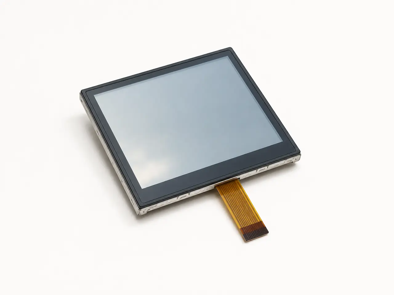
Review the FPC as a mechanical part
The FPC must reach the board without interference or excessive stress. The routing should be reviewed with the enclosure, connector height and assembly sequence.
- Exit position and routing path
- Bend radius and keep-out zones
- Stiffener thickness and component clearance
- Tolerances and assembly access
Build a focused sample test
The first sample test should confirm communication, image stability, backlight control, touch when applicable and repeatable assembly—not only whether the display turns on.
- Power-up and initialization
- Full-pattern and color checks
- Temperature and cable-movement checks
- Final drawing and pinout sign-off

