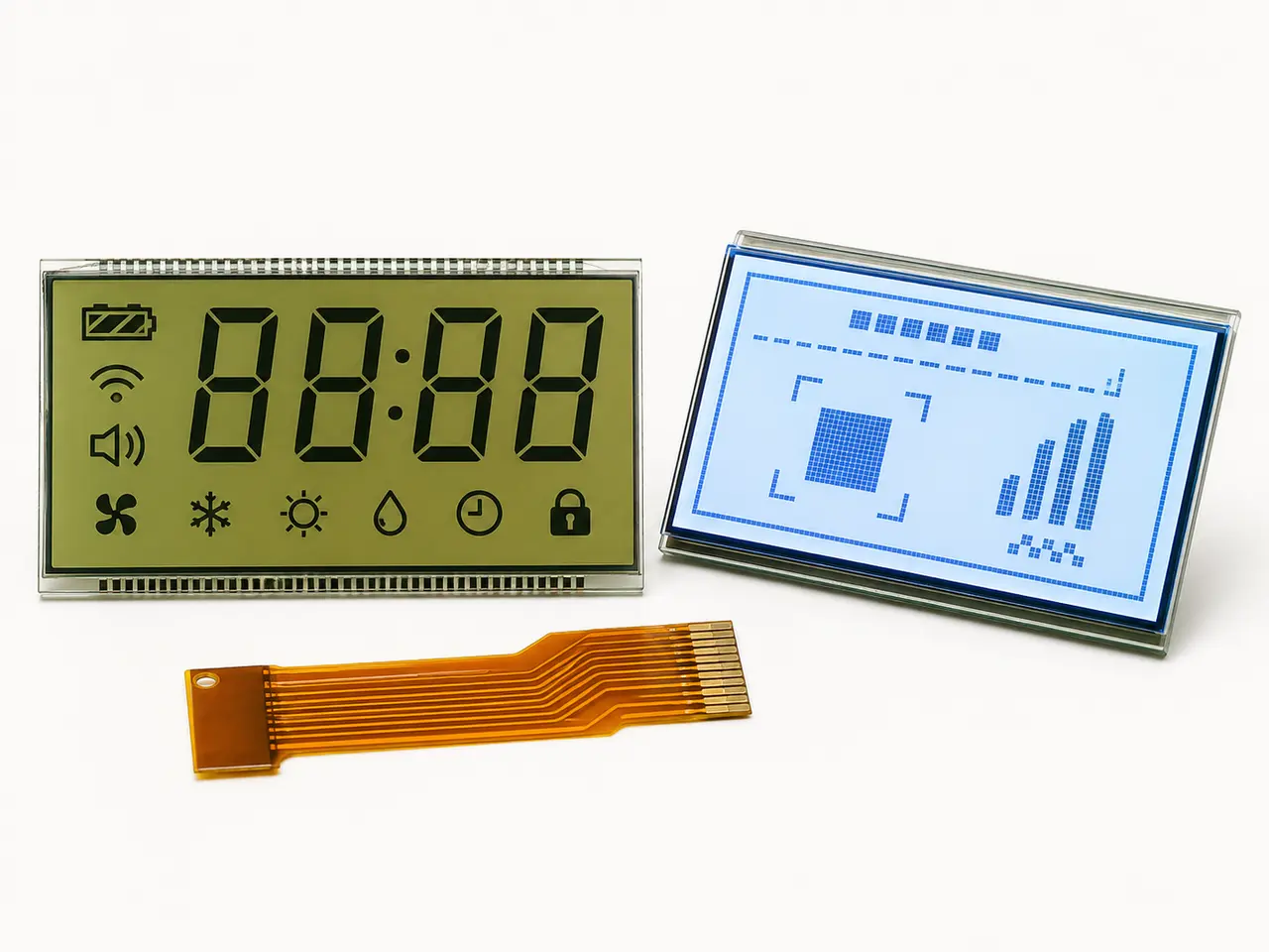
Why flying insects gather around a working dehumidifier display
Basements and equipment rooms are often relatively dark, so an illuminated LCD backlight becomes a high-contrast local light source. Controlled studies show that artificial point light can disrupt the flight orientation of multiple insect groups, while other experiments show that response varies with species, spectrum and wavelength. In practice, the dehumidifier backlight may therefore bring susceptible flying insects close to the front panel, especially when it is one of the brightest objects in the space.
- Backlight visibility increases when the surrounding room is dark.
- Insect response depends on species, wavelength, intensity and environmental conditions.
- Reducing brightness may change attraction, but it does not close a mechanical entry path.
- The engineering target should be ingress prevention rather than an assumption that light can be eliminated.
The key diagnosis: attraction is not the same as entry
Seeing insects around the display and finding insects inside the display are related but different observations. The backlight can draw insects toward the product; a structural opening allows them to enter. If the assembly includes a channel between the metal frame and PCB, an incomplete tape seal, an uneven corner or an unsealed backlight edge, small insects can move behind the viewing area and become visible to the user.
- Inspect the full contact line between the metal frame and PCB.
- Look for corner lift, frame distortion and PCB bowing.
- Check all four backlight edges for missing, wrinkled or discontinuous tape.
- Review openings near the FPC exit, connector and assembly features.
Solution 1: make the metal frame sit flush with the PCB
The metal-frame height should be designed so the frame seats evenly against the PCB in the final assembled condition. The objective is not simply to make the frame shorter; it is to eliminate a continuous passage while preserving the intended compression, optical stack height and mechanical support. Frame height, PCB flatness, component clearance and assembly tolerance should be reviewed together on the drawing and on real samples.
- Define a controlled frame-to-PCB contact or maximum permissible gap.
- Check contact around the complete perimeter rather than at one measurement point.
- Avoid excessive force that could warp the PCB, stress the LCD or change display uniformity.
- Lock the approved frame revision and tolerance in the production drawing.
Solution 2: seal all four sides of the backlight
After the mechanical path is closed, apply a continuous perimeter seal around the backlight using high-temperature adhesive tape selected for the product environment. All four sides must be covered so that the tape forms one complete barrier. Small isolated tape pieces can leave corner channels. The tape should also help control side light leakage, but it must not cover the visible area, electrical contacts, LEDs, or a functional opening required by the approved design.
- Use tape with temperature, humidity, adhesion and electrical properties suitable for the appliance.
- Seal each corner without wrinkles, lifted edges or exposed channels.
- Keep the FPC bend zone and connector contact area free from unintended stress or adhesive.
- Standardize tape width, overlap, placement and inspection criteria for production.
Why brightness reduction alone is not a reliable fix
Lowering backlight intensity may make the display less conspicuous under some conditions, but it can also reduce readability and still leave the product open to insects, dust and fibers. Changing color or spectrum may affect particular insects, yet response is species-specific and cannot replace a physical barrier. A product that needs a readable illuminated display should be engineered so that nearby insects cannot reach the optical stack.
- Do not trade away user readability before correcting the assembly gap.
- Do not treat a different LED color as a universal insect-proof solution.
- Use optical changes only as a supplementary measure after ingress paths are controlled.
Production validation checklist for an insect-resistant LCD assembly
The modified display should be validated as a complete dehumidifier control assembly. A visual check is useful, but repeatable measurements and environmental aging provide stronger evidence that the frame and tape will remain sealed during production and service.
- Inspect the perimeter under magnification and record any measurable frame-to-PCB gap.
- Use a dark-room light-leak check to reveal open backlight edges and corners.
- Confirm tape continuity, overlap, adhesion and edge lift after temperature and humidity aging.
- Run the display through power, brightness and full-pattern checks to verify optical uniformity.
- When appropriate, perform a controlled dust or small-particle ingress assessment on the final enclosure.
How to repair an existing dehumidifier display with insects inside
Disconnect the appliance from power and have qualified service personnel open the control assembly. The display may be cleaned only if the optical layers have not been stained or damaged. The technician should then identify the original entry path, correct the frame fit and install a complete perimeter tape seal before reassembly. Replacing or cleaning the display without closing the path allows the problem to return.
- Photograph contamination and gaps before disassembly.
- Avoid touching polarizers, light-guide surfaces and exposed contacts.
- Replace damaged optical films or the display module when cleaning cannot restore appearance.
- Repeat the gap, light-leak and functional checks after repair.
What OEM buyers should specify to the display supplier
For a new or replacement basement dehumidifier LCD, the RFQ should include the mechanical drawing, PCB outline, stack-up, FPC exit, operating temperature, humidity exposure and photos of any field contamination. State that the display must use a flush frame-to-PCB interface and a continuous four-side backlight seal, then agree on how the requirement will be inspected and approved.
- Maximum frame-to-PCB gap and frame-height tolerance.
- High-temperature tape material, width and approved application method.
- Four-corner sealing and light-leak acceptance criteria.
- Environmental aging, display function and cosmetic inspection plan.
- Golden sample, revision control and traceable production records.