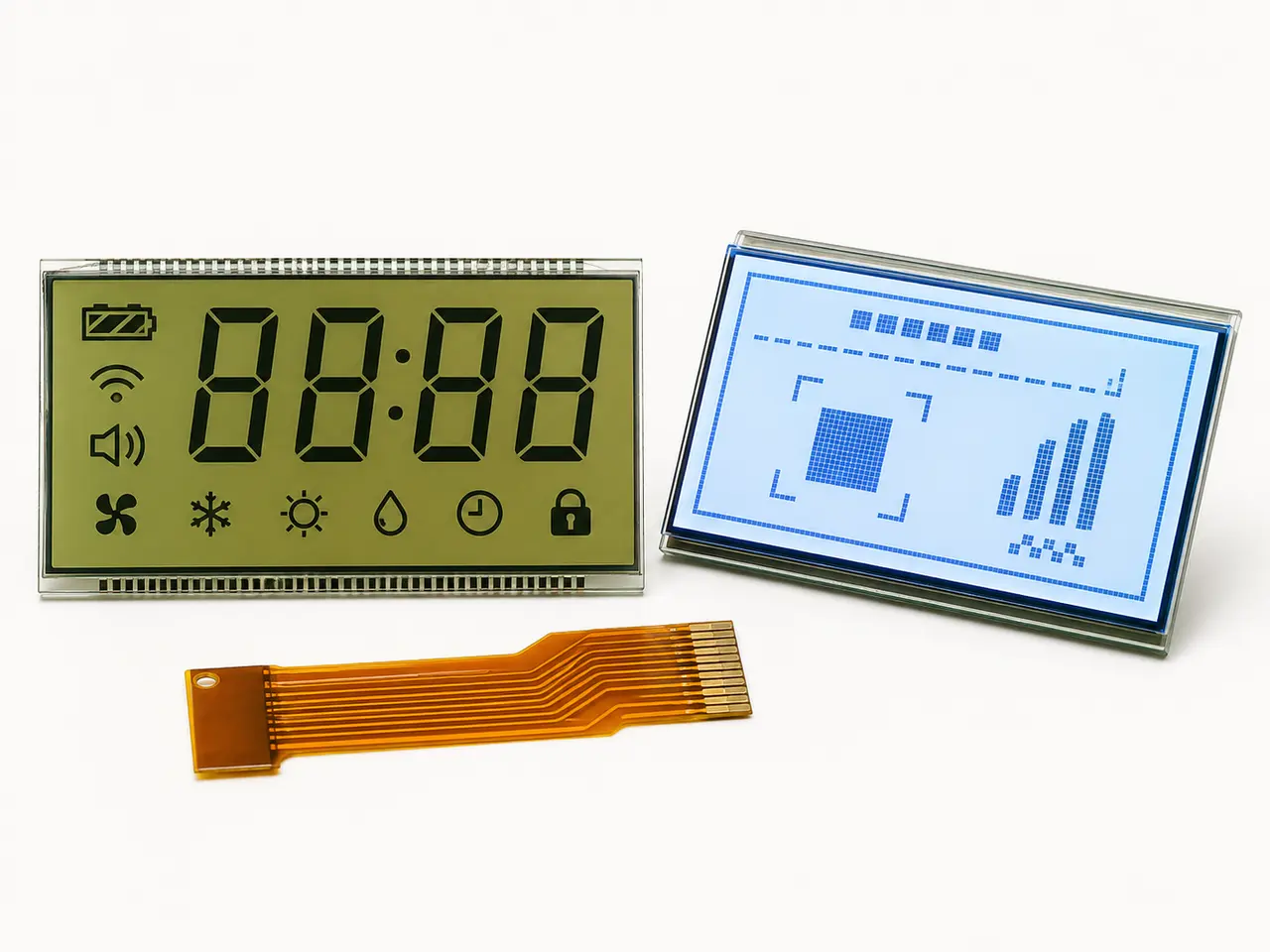
1. Begin with the information the product must display
A custom monochrome LCD should be defined from the user's task. If the screen shows a fixed collection of numbers, units, icons and status symbols, a segment LCD can provide a simple, low-power solution. If menus, changing text, graphs or multiple layouts are required, a dot-matrix graphic LCD is usually the more flexible path. Decide which content is fixed and which content must change before drawing the glass outline.
- List every number, unit, icon, warning and annunciator the user must see.
- Identify content that is always fixed and content that changes by mode or language.
- Define the smallest acceptable character and symbol size at the intended viewing distance.
- Confirm whether the future product roadmap requires additional screens or translated text.
2. Choose segment LCD or graphic LCD deliberately
Segment displays place each symbol directly into the glass artwork, so they are efficient when the user interface is stable. Graphic LCDs use a pixel matrix and controller, which supports flexible content but adds resolution, memory, firmware and interface decisions. Neither type is universally better: the correct choice is the one that meets the information requirement with the least unnecessary complexity.
- Choose segment LCD for meters, appliances, thermostats, instruments and repeatable status layouts.
- Choose graphic LCD for menus, variable text, multiple languages, waveforms or changing icons.
- Review firmware resources and controller support before committing to a graphic resolution.
- Avoid converting a simple fixed UI into a pixel display unless flexibility creates real product value.
3. Match the optical mode to the real viewing environment
The same artwork can look very different depending on the LCD mode, polarizer and backlight. Reflective displays use ambient light and suit bright environments with very low power. Transmissive displays rely on a backlight and suit controlled indoor viewing. Transflective displays balance ambient-light readability with an illuminated night mode. Positive or negative appearance, TN, STN, FSTN and VA options should be evaluated against the actual viewing angle, contrast, color target and power budget rather than selected only from a catalog photograph.
- Record indoor, outdoor, sunlight, night and low-light use conditions.
- Define the normal viewing direction and any off-axis readability requirement.
- Choose positive or negative appearance from the complete day-and-night UI requirement.
- Specify the backlight color, brightness-control method and acceptable light uniformity when illumination is required.
4. Freeze the mechanical envelope before detailing the connection
The display outline, visible area, glass thickness, seal area, mounting method and connector position must fit the complete product stack. A display that meets the electrical requirement can still fail if the viewing window clips icons, the FPC cannot bend safely or the connector conflicts with the enclosure. Review the LCD, PCB, bezel and assembly sequence in the same mechanical drawing.
- Provide the maximum outline and the required visible area in millimeters.
- Mark the viewing side, display centerline and orientation in the final product.
- Show keep-out zones, mounting pressure points and the path from display to PCB.
- Include tolerance stack-up for the bezel opening, PCB position and display alignment.
5. Select PIN, FPC, COG or COB from the assembly and controller
PIN connections can be straightforward for low-pin-count segment displays and manual assembly. FPC provides more routing freedom and can combine connections with selected components. COG places the driver IC on the glass for a compact module, while COB places the controller on a PCB and is common in graphic modules. The decision affects thickness, pin count, tooling, assembly process, serviceability and controller design, so it should be made with the product engineer and display supplier together.
- Use an annotated drawing to identify pin one, contact side and connector orientation.
- Confirm FPC exit position, length, pitch, stiffener and minimum bend radius.
- Name the driver or controller when it is already selected, or provide the host MCU details for review.
- State whether the customer assembles bare glass, a display module or a display-PCB subassembly.
6. Document the electrical drive conditions
A monochrome LCD is not defined by outline and artwork alone. Segment glass requires compatible drive voltage, duty and bias; graphic modules require an agreed controller, command set, interface and initialization. Incorrect drive conditions can create poor contrast, ghosting, unstable appearance or reduced service life. The approved drawing and specification should therefore contain the electrical values used for sample validation.
- Logic and LCD drive voltage, including allowed tolerance.
- Duty, bias and frame frequency for custom segment glass.
- SPI, I2C, MCU or other interface definition for controller-based modules.
- Pin assignment, timing, initialization and backlight electrical requirements.
7. Define temperature, humidity and lifecycle requirements
The display must be selected for the product environment, not only room-temperature appearance. Operating and storage temperature influence fluid, polarizer, adhesive, backlight and connector decisions. Humidity, condensation, UV exposure, vibration and cleaning chemicals can also change the required construction. Forecast and product lifetime matter because material continuity, tooling and change control must support repeat production.
- State operating and storage temperature ranges separately.
- Describe humidity, condensation, UV, vibration and chemical exposure when applicable.
- Provide prototype quantity, estimated annual volume and expected production years.
- Agree how material or process changes will be communicated after approval.
8. Approve the sample in the complete product
A bench sample can confirm basic appearance and communication, but it cannot prove product fit, viewing angle, sunlight performance, night dimming or long-term assembly stability. Test the display with the real controller, PCB, bezel, backlight settings and representative environmental conditions. Record the approved sample, drawing revision, firmware version and acceptance criteria as the production reference.
- Check every segment or full pixel pattern for missing, weak or unintended content.
- Verify contrast, viewing direction and backlight uniformity inside the enclosure.
- Test power-up, initialization, dimming and the expected operating modes.
- Complete representative temperature and environment checks before mass-production release.
- Retain a signed golden sample and controlled drawing for incoming inspection and change review.
Information to send for a useful engineering review
A complete specification is helpful, but it is not required for the first conversation. A marked sketch, current display sample or photograph can establish the starting point. The most useful inquiry connects the visual requirement, mechanical envelope, controller, operating environment and expected quantity in one package.
- Segment artwork or graphic resolution, plus the visible-area requirement.
- Maximum outline, thickness, connection position and product cross-section when available.
- Controller or MCU, voltage, interface and any known duty or bias values.
- Viewing direction, optical appearance, backlight and operating environment.
- Prototype quantity, annual demand, target schedule and expected product lifetime.
